Why continuous text is a thing of the past
Today, medical device development is caught between increasing pressure to innovate and growing regulatory requirements. Products are becoming more complex, often with a high software content, and need to be brought to market faster. The EN 14971, EN 62304 and EN 62366 standards set clear benchmarks – and demand full proof of safety, functionality and usability.
Many companies try to manage this balancing act using traditional means: Word documents, Excel spreadsheets, manual review processes. The result is a cumbersome mountain of documentation, inconsistent data, and processes that no longer meet the demands of modern product development.
This is both the problem – and the opportunity.
An integrated data model breaks with these old habits. It replaces unstructured text with well-defined, logically related data objects. Requirements, risks, test cases – everything is linked, auditable and automatable. Instead of fragmented information, you get a transparent, controllable development process that not only meets standards, but also gives you the freedom to focus on what matters: a safe, innovative, and market-ready product.
This article shows how you can use intelligent data models:
- Master the complexity of product development,
- Eliminate sources of error at an early stage,
- Use resources efficiently and
- not only perform standards-compliant verification, but also integrate it elegantly.
Through real-world examples, you will learn how data models are the key to greater quality, speed, and security. Designed for anyone in the MedTech industry who wants to create, not just manage: Developers, usability and risk managers, quality managers – and decision makers who know the difference between mediocrity and market leadership.
Continuous Text: The Blind Spot in the Development Process
In many engineering departments, Word documents and Excel spreadsheets are still the foundation of requirements and risk management. They have worked well for decades, but in a world where products are becoming more complex and standards are becoming more stringent, these tools are no longer sufficient.
Typical weaknesses of continuous text documentation:
1. Redundancies and inconsistencies:
- Information is often recorded more than once, or identical statements vary verbally.
- Redundant information has to be manually changed in many places.
- Different document versions lead to misunderstandings.
2. Lack of link ability:
- Requirements, risks and test cases are separated, often in different documents or files.
- No automatic traceability – traceability is usually done in complex and error-prone Excel spreadsheets.
- Connections are only established through the interpretation of those involved.
3. Error-prone and time consuming:
- Manual consistency checks are error-prone and time-consuming.
- Gate reviews become a mammoth task, often with incomplete results.
- Audits by notified bodies mercilessly expose weaknesses.
4. Lack of real-time visibility:
- Status changes are not immediately visible.
- Progress in some areas remains invisible.
- Early risk mitigation is hampered because warning signals are often detected too late.
Continuous texts are too flexible - and that is precisely their problem
They leave room for interpretation, which can be fatal for safety-critical products. When requirements are not clear, tests are not properly documented or risks are not transparently assessed, it’s not only the quality that suffers – costs, delays and legal risks also arise.
Why data models are clearly superior here:
- They enforce clarity: only structured data is accepted.
- They eliminate redundancy: each artifact exists exactly once – relationships instead of copies.
- They enable automation: checks run continuously, not just selectively.
- They provide control: every change is documented, every relationship is visible.
Continuous text may be useful for initial concepts – but if you want to develop complex medical devices, you need a systematic approach. And that starts with moving away from Word and Excel as your primary tools.
Fundamentals of Efficient Data Models
What is a Data Model?
A data model describes the structured representation of all relevant information of a product in the form of linked objects (artifacts or items) with clearly defined attributes. Unlike documents, where information is often implicit, each piece of information is explicitly recorded in a data model and can be automatically analyzed.
Structure of a Data Model
Data Objects
A data model consists mainly of data objects. These can be, for example, Requirements, Test Cases, Risks or Defects. Each of these objects has a unique ID and attributes that describe the object. These attributes can be mandatory or optional
Attributes
The following figure shows possible attributes that can be used to define a requirement in more detail. For example, it is useful to separate the prerequisite for a requirement from the actual requirement. This ensures that requirements are defined more precisely. This is important because, for example, an “if-then” condition and an “exactly-then” condition may sound similar, but they are very different in terms of the required test design. It is also very helpful to clarify the “why” question in a requirement, because there may be different intentions for many design decisions, and these intentions in turn have a critical impact on the criticality in risk assessment when you need to analyze what happens if a design element does or does not perform as specified.
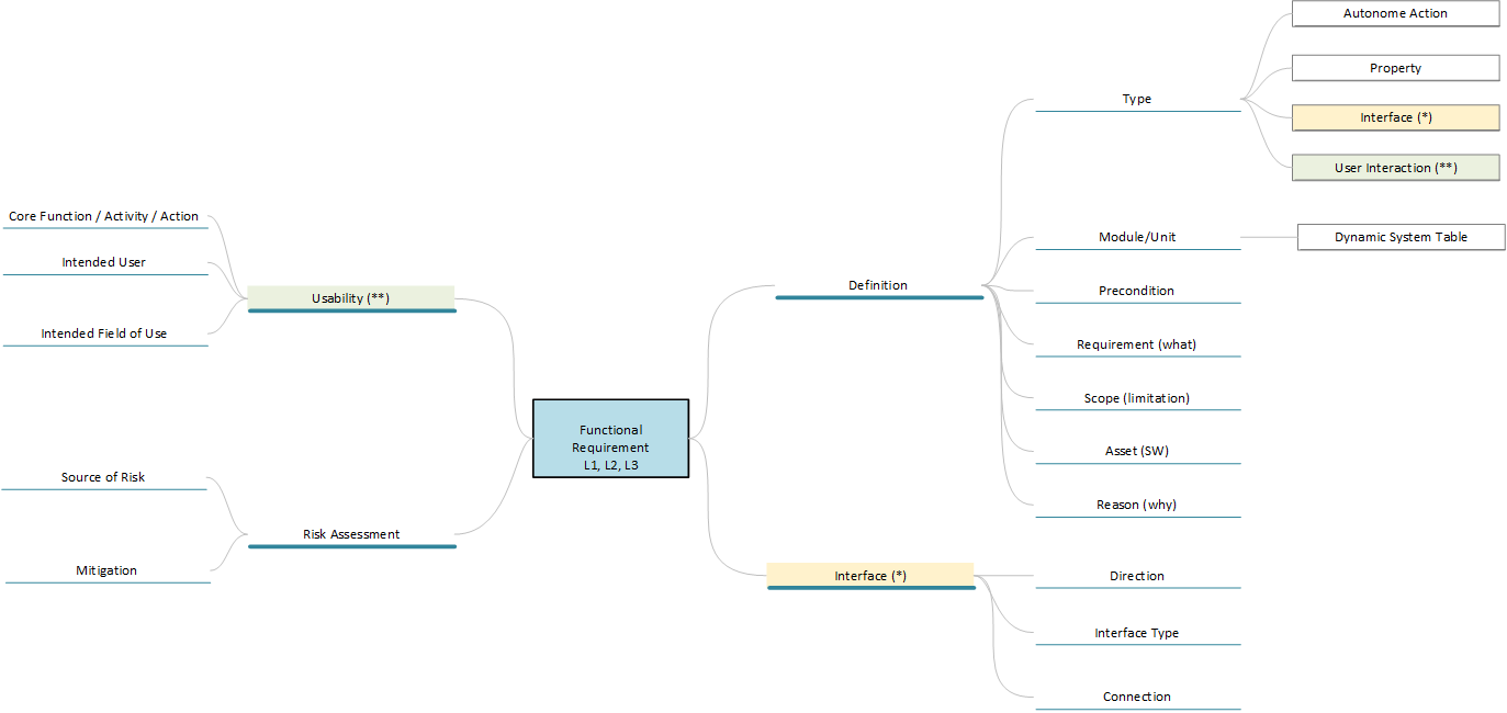
Free text or continuous text should also be avoided in the attributes. This reduces errors in interpreting the data and improves machine processing. Also, do not use checkboxes. Although they are very easy to handle, in case of doubt it is not possible to determine whether a checkbox is empty because the author wanted it that way or because he did not edit it.
Workflows
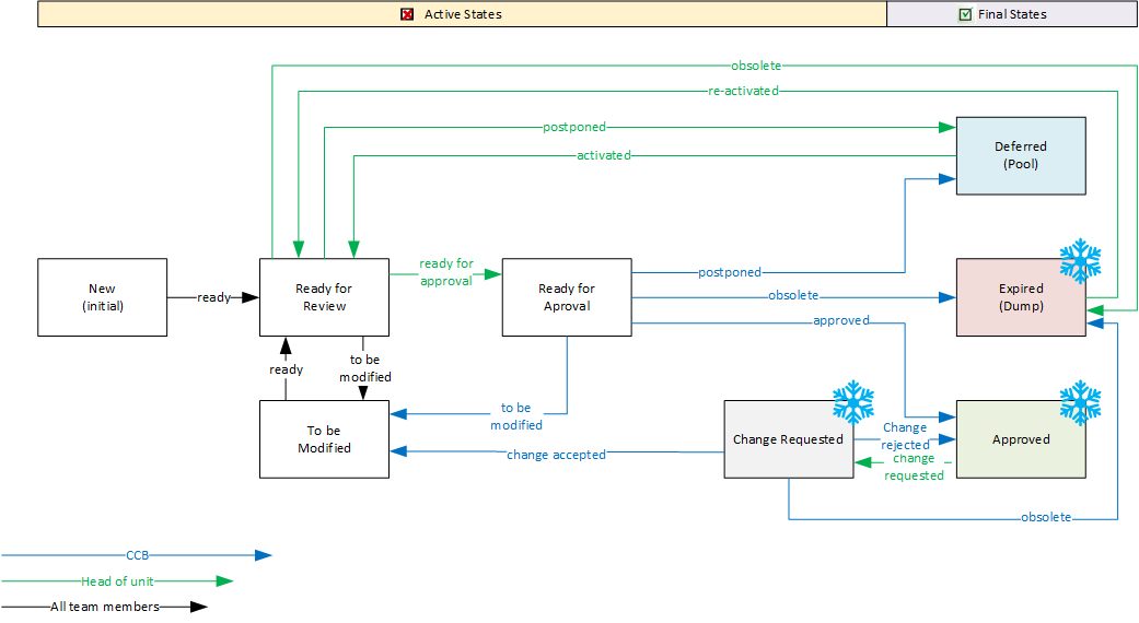
A workflow is actually a status attribute, except that its values reflect the processing status of the data object and its values can only be run through on certain paths.
The following illustration shows a possible workflow for a requirement, where the active phase represents the possible processing and review steps, and a requirement can ultimately be marked as “Approved” or “Deferred” for a later cycle. Note also that a requirement can be “expired” as an object is not removed from the model for a complete history. When process transitions are restricted to authorized groups of people and linked to systematic data checks, you have a powerful project management tool.
Relations
Relations describe the connections between two or more data objects. For example, a test case checks the implementation of a requirement as a “definition of done”, or several risk mitigations are related to the risk to be mitigated. It is also possible to relate data objects of the same type. For example, a requirement can be related to another requirement because they are interdependent in the design, or because they describe an interface between design elements.
Because a data model uses a large number of Relations, it is also important to name these types uniquely, as they are often the basis for queries and analyses. There are several ways to do this. The parent-child relationship has proven to be useful, with the following basic rules:
- A child object always references a parent object, i.e. the direction of flow of the relation is always from the child to the parent object
- The relation is always named in the direction of flow “[child] is related to [parent]”.
For example, a relationship between a test case and a requirement can be named as follows “[Test] checks [Requirement]” (see figure below).

Practical Advantages
As can be seen from the description, such a data model offers many practical advantages. The three most obvious ones are:
- Automated checks
Data can be found based on automated queries, such as “Show all requirements of type ‘interface’ in assembly ‘A'” or “Show all requirements that have no test case”. The options scale with the granularity of the data model and can also be automatically combined into complete audit trails. - Flexibility & Scalability
Models can be extended iteratively by adding new data types or extending existing data types with new attributes. Unlike continuous text, adding new attributes is straightforward because there is no syntactic morphology to worry about. - Standardization
The attributes in the data objects correspond to the forms to be processed. They are like a checklist and ensure that all the necessary information of a design artifact is captured. They guarantee a uniform approach and style in the development documentation. This is a fundamental preparation and prerequisite for the introduction of product platforms, where a portfolio of modules is recombined into different products.
Improved depth of focus: Traceability as a Systemic Control Element
Traceability – the ability to trace all possible causal relationships in product development – is not only a regulatory must in the medical device industry, but also a critical quality factor. Standards such as EN 14971, EN 62304 and EN 62366 require it – but an intelligent data model takes traceability to a new level: from a burden and expense to a strategic advantage.
In design models, the relationships between design artifacts can be very diverse and complex. This is not a problem in the sense that such relationships can be very well managed and monitored by machines – databases.
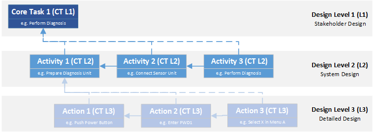
Many design models look at the product from different levels or perspectives. EN 62304 defines three levels. Although this standard refers specifically to the development of software for medical devices, the concept is common to many model approaches and can be generalized to any type of product development.
- The stakeholder level is the first layer of the design model. From here, you have a monolithic view of the product and focus on the features or benefits the product must have to meet the needs of the various stakeholders associated with the product.
- The system level comes after the stakeholder level. Here, the technical concept is designed to meet the requirements of the stakeholders. Based on the selected technologies and the tasks to be performed, modules are defined that must perform certain subtasks and thus interact with each other and with their environment.
- The third level is the design output. It defines the specific technical implementation for each system module. It is therefore the technical blueprint from which the product is ultimately built.
Based on these design levels, two directions of traceability are considered – vertical traceability, the relationships between design levels, and horizontal traceability, the dependencies within a design level.
Vertical Traceability
Vertical traceability shows how each requirement is passed from one level of abstraction to the next – from stakeholder requirements to functional system architecture to actual implementation. In other words, it must be ensured that every requirement at a higher level is covered by at least one requirement at a lower level. There may well be requirements at the lower level that have no obvious connection to the higher level because they arise from the need for the new design perspective.
For example, if a stakeholder, such as an emergency physician, requires that he or she be able to perform a certain diagnosis completely independent of external conditions, and this diagnosis requires a technology that requires electrical power, the system architect must define a module that provides the required power. He can decide whether the required energy is generated on demand or supplied from an energy storage system. If he chooses to use an energy storage system, the product designer must design the appropriate storage media, rectifiers, and chargers with all the schematics and specifications at Level 3 so that the power source of the device meets the required performance requirements. This means that the requirements of one level are linked to the requirements of adjacent levels. Data models make this chain transparent, so that changes to a requirement at one level automatically trigger checks of the associated requirements.
Horizontal traceability
Horizontal traceability ensures that everything within a design layer fits together. One of the most fundamental relationships in a design specification is the aforementioned relationship between requirement and test, called the “Definition of Done”. This relationship ensures that the implementation of each requirement is verified or validated. Conversely, requirements can be more easily identified in root cause analyses when tests fail or bugs are reported in a product. Sometimes such failures also lead to the discovery of gaps in the design specification, because the failures can be traced back to requirements that were not clearly defined for the product.
As the flight altitude in the design levels decreases, the complexity between the data objects increases. This applies both to the information content of individual design artifacts and to the relationships between them. It can only be emphasized that well-structured data with unambiguous attributes and clearly distinguishable link types is an essential prerequisite for mastering this complexity.
The relationship between requirements, risks, and mitigations can also be mapped and monitored. This concept is discussed in more detail below.
Staying with the example of our diagnostic device, another requirement might be that the device must have a high level of reliability. The system architect addresses the risk of the power module failing with two mitigations – a redundant power supply design and an emergency switchover device. This results in three test cases, the implementation of the additional devices and their effectiveness in the event of a failure.
Each of these components is interconnected at the system level. A change in the specification of the power supply (e.g. a higher load consumption) automatically affects the risk, the mitigation design and the test plan.
The Meta-Level of Traceability - Organizational Implications:
Traceability is not a bureaucratic act – it is the compass that guides you through the regulatory requirements. A data model ensures that you never lose your bearings. It is not only a project tool, but also:
- Audit Tool: Complete information on processes and consistent, standard-compliant documents at all times.
- Quality control: Logical checks minimize sources of error.
- Knowledge management: Reusable modules and requirements for future projects.
- Ensure compliance: Direct link to standards and regulatory requirements.
The data model in use
Risk management - integration and depth
A key challenge in the development of medical devices is risk management in accordance with EN 14971. It must be ensured that risks are systematically identified and that appropriate design changes or risk reduction measures and user information are implemented.
Integration of EN 14971
Systematic identification of risks
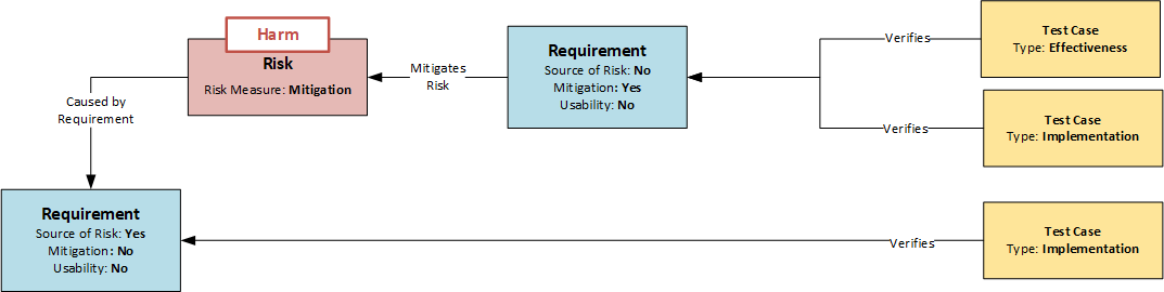
The first crucial point is the systematic identification of risks. A method often used in practice is the risk assessment of the device based on a catalog of issues. This involves assessing whether risks of a certain category are to be expected for the product in question. If so, they are identified (top-down analysis). The method is systematic, but does not guarantee the completeness of the results. A much more in-depth analysis is possible if each requirement is examined as a potential source of risk. This analysis can be controlled by an attribute in the Requirement data object. If a requirement turns out to be the source of a risk, it is briefly described and marked by setting the “Source of Risk” attribute (see figure: Model of Dependencies between Requirements, Risks and Test Cases). This would be the bottom-up analysis, where all requirements of the product are systematically examined.
The identified risks must now be assigned at least one data object of the risk type. This data object describes the risk in more detail using a list of predefined attributes. By using the same risk categories for the attributes, the bottom-up and top-down analysis can be combined, which reduces the error susceptibility of the method, similar to the two-account method in accounting. Several risks can be assigned to a requirement or the same risk can be assigned to several requirements.
In contrast to tables, risks are no longer dead lists, but networked nodes in the system that are sensitive to changes.
Mitigations are requirements
If it is decided to minimize the risk, mitigations (risk-reducing measures) are defined to reduce the probability of the risk occurring. These are design requirements. To identify them as special requirements in risk management, they are given the attribute “mitigation” and refer to the risk or risks they are intended to minimize (see figure: Dependency Model between Requirements, Risks and Test Cases). In this way, the reference to the risks can also be recognized in the event of subsequent design changes.
EN 14971 requires that the mitigations themselves be checked for possible risks. Since all requirements in this model are checked without exception, this requirement is met.
Implementation and Effectiveness
Another important aspect is the verification of effectiveness. As mentioned above, each requirement is assigned at least one test case to check the implementation of the requirement. However, if a requirement is marked with the attribute “mitigation” (see figure), the effectiveness of the measure has to be checked in addition to the classical implementation test according to EN 14971. Therefore, two tests are required:
- Implementation test: Has the mitigation measure been implemented correctly?
- Effectiveness test: Does the mitigation really reduce the risk to an acceptable level?
Accordingly, there are different types of test case data objects. In the simplest case, the distinction can again be made via an attribute, as shown in the following figure. With the help of the respective attributes “Implementation” and “Effectiveness”, the correct test coverage can be plausibly monitored by a corresponding query of relations and attributes: “Show all requirements with the attribute ‘Mitigation’ that are not covered by at least one test case with the attribute ‘Implementation’ and at least one test case with the attribute ‘Effectiveness’.
Completeness of a Design Level
Mitigations always ultimately lead to one or more design outputs. However, in order not to leave any “open ends” with regard to the necessary requirements at design levels (1) and (2), it is advisable to mitigate the risks at the design level where they were identified. This also has the advantage that the necessary actions are defined from the same design perspective from which the problem was identified. No mental leap is required. On the other hand, it is possible to perform a self-contained check in the gate reviews when leaving a design level – a risk is to be reduced and at least one action is defined to do so. The requirement for design coverage already mentioned for vertical traceability, i.e. each requirement at a higher level should be covered by at least one requirement at the next level, ensures that all measures are passed through to the design output. This means that once requirements are identified, they stay on the radar until the end.
Summary - Risk Management Model
The following statements can be summarized for risk management using the data model shown in the diagram above:
- Requirements are described in the Requirement data object
- Each requirement is systematically examined to determine whether a risk can arise from the design if it functions correctly or incorrectly; if so, it is assigned the Source of Risk attribute.
- Risks are described in the Risk Data Object and refer to the source(s) (requirements) from which they arise.
- When a risk is minimized, it is done through mitigation.
- Mitigations are requirements that are subject to all the requirements of the requirement. They receive the attribute “Mitigation”.
- Requirements with the attribute “Mitigation” are checked not only for their implementation, but also for their effectiveness in minimizing risk.
Depth of Analysis
Integrating risks as nodes in the big data network shows which requirements they arise from and which measures can be used to control them. Any design change can therefore be made in a risk-sensitive manner. You can also quickly see the impact of a particular risk and how many subsystems it may affect.
You can also use the information about risk relationships to prioritize your development resources so that you can implement the most effective safeguards in the right places.
By separating the severity of the damage from the risks into independent data objects-which further reduces the effort and standardizes the risk assessment-you can also see which risks cause the same or similar damage, which brings many benefits to the overall risk assessment.
Usability Engineering: Process Integrated Safety
Accurate Implementation of EN 62366
From Actions to Requirements
The interaction with a medical device can also be integrated into the perspective of the design levels. An action is the interaction with the product as a whole – the doctor wants to obtain an ECG. To do this, he interacts with individual functional assemblies – he applies electrodes and works with the user interface of the measurement amplifier. To do this, he uses buttons, operates switches or reads scales. In other words, all these actions, activities, and interactions are related to requirements at the appropriate levels that define these user interactions.
Identification of risk-critical interactions
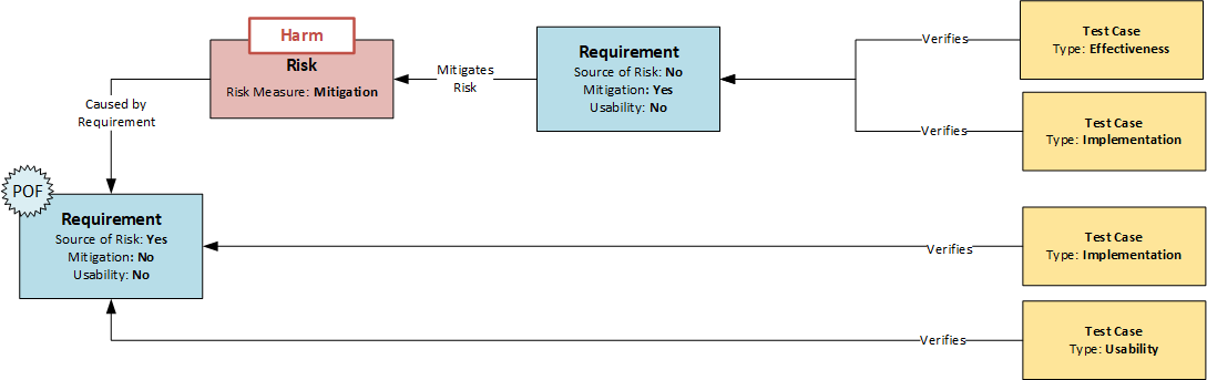
EN 62366 introduces the concept of “Primary Operating Functions” (POF). These are functions directly related to the safety of the medical device. In its guidance: “Applying Human Factors and Usability Engineering to Medical Devices” (FDA Guidance 2016), the FDA uses the term “core function”, which has a similar structure. Identifying these functions is an important step in the usability engineering process and can be integrated into the data model presented here.
For this purpose, all requirements that refer to actions and thus define the system-side user interaction are assigned the attribute “Usability”. If a requirement with the attribute “Usability” is also the source of a risk (“Source of Risk” attribute), safety-relevant functions in the operation of the device are identified and can be further processed on the basis of the normative requirements. As already described for mitigation, there are further possibilities for monitoring. For example, such requirements must not only be tested with regard to their implementation, but also require additional usability tests, which must be carried out as formative tests at the system and design output level and as summative tests at the stakeholder level.
Information for the usability file
The entire development of medical technology is risk-centered, so that EN 62366 and EN 14971 are also closely related. Usability risks can therefore be recorded in a standardized risk management process without deviating from the procedure described above. In order to transfer usability risks to the usability file, all risks whose “source of risk” has the attribute “usability” are collected. In this model, usability risks are only a subset of the total risks.
Summary - Usability Engineering Model
The following statements can be summarized for Usability Engineering using the integrated data model (see figure below):
- If a requirement is directly related to a user interaction, it is assigned the attribute “Source of Risk”
- If requirements with the attribute “Usability” are also the source of a risk – i.e. receive the attribute “Source of Risk” – they indicate a safety-critical interaction (primary operating function)
- Requirements with the attributes “Usability” and “Source of Risk” should not only be tested with regard to their implementation but also with regard to usability (summative/formative).
- All risks whose “source of risk” has the attribute “usability” are transferred to the usability file as risks.
Depth of Analysis
The presented procedure has a very systematic approach, with which usability risks can be identified with a high degree of certainty. If the target groups of the users for whom this functional design was planned, e.g. doctors, nurses, patients or service technicians, are also recorded in the “Usability” type requirements, this information can be automatically transferred to the test design. Based on this information, test runs for summative usability tests can be planned specifically for certain target groups. The same applies to interactions related to requirements. Test scenarios for usability tests can be derived from the data model.
However, the link also allows working in the opposite direction. Any error in the usability test flows directly back into the risk file and can trigger a reassessment of the risks.
Tools and Implementation: From Theory to Operational Excellence
Why Classic Tools Fail - and Specialized Systems Make the Difference
The demands placed on modern medical device development processes are high – and rising. Documentation requirements, verification management, change management, integration of standards: All of this can no longer be reliably managed with traditional office tools.
Core problems of classic tools (Word/Excel):
- No structured data storage
Information has no specifications as to form or content – and when it does, it is highly dependent on the discipline and skills of the teams. In other words, there is no common thread to guide you through your task. The relationships between artifacts cannot be systematically recorded. They are usually embedded in the context of headings – but what if you want to change the perspective? - Manual maintenance
Document-centric information in rigid structures often results in redundant content. This increases the time and effort required to create it, especially if changes are necessary. Have you ever thought about how many documents you reference to the intended use of your council? The logic by which you can maintain your data is also extremely limited, and again much depends on the skills and discipline of your reviewers. - Limited scalability
The number of artifacts grows with the complexity of your products or the diversity of your application options. 1,000+ requirements are not uncommon, add testing and risk, and it gets confusing. Did you know that traceability matrices grow exponentially, not linearly? It gets even more complex when you recombine design modules into a product platform. But product platforms in particular have high economies of scale and offer ideal opportunities to diversify your product portfolio.
Requirements for a Professional Data Modeling Tool
- Object-Oriented Data Management
Any desired information can be clearly defined and identified in a specially created object. The system is scalable and grows with your needs. Information is captured comprehensively, resulting in consistent and well-balanced documents and specifications, even when large teams are working together. - Automated traceability mechanisms
By linking data objects, Excel spreadsheets and Word lists become networked data points in model space along which you can move horizontally and vertically through your design model. Dependencies and conflicts become transparent and can be identified early on. Data cuts from different perspectives answer a wide range of questions – e.g. design and test coverage or impact analyses. - Integrated Change Management
Not only do you have access to all the information, but you can also drill down into its history to trace correlations and decision paths for changes (who, what, when, why?). The data network enables precise impact analysis – no more unexpected domino effects. - Workflow-Controlled Release Processes
Project management and process control are based on the data objects. Individual and process-optimized workflows control the design process. Role-based management for inspectors and approvers enables comprehensive controls that can be supplemented with electronic signatures (FDA21 CFR Part 11 compliant). - Extensibility & Interfaces
Scalability is not limited to information and data. Additional tools, e.g. for test automation, can be integrated. Documents can be generated, controlled and managed from the data model. Interactive dashboards provide real-time process control and visibility.
Summary Comparison of Typical Systems
The following overview summarizes the capabilities of an integrated data model compared to working with Word or Excel.
| Function | Word/Excel | Tool with Integrated Data Model |
|---|---|---|
| Traceability | Manual, error-prone | Automated, seamless |
| Change Management | Not traceable | Fully documented |
| Standards Compliance | Manual check | Integrated validation logic |
| Scalability | Low | High, even with 10k+ objects |
| Collaboration | Via email, cumbersome | Centralized, role-based |
| Auditability | Laborious, uncertain | Real-time ready |
Conclusion
With an integrated data model, you’re not just driving safely – you’re driving ahead.
Medical technology is not standing still – and if you want to keep up, you have to be willing to break old habits. Data models are not just a trend; they are the logical consequence of increasing complexity, stringent standards, and a market that is unforgiving of mistakes.
While we have only scratched the surface of the power of integrated data models, their potential for any development department is more than obvious.
With an integrated data model:
- Master complexity: with structured, interconnected data instead of confusing text deserts.
- Proactively meet standards with automated checks, seamless traceability, and auditable change management.
- Increase efficiency: Less manual work, faster reviews, targeted testing.
- Improve product quality: early defect detection, improved usability, robust risk management.
- Become more agile: Change is no longer a risk, but part of your innovation strategy.
The future belongs to those who control their data.
If you’re curious and don’t want to take this step alone, we are a partner who offers not just tools, but solutions. Contact us to learn how your organization can realize the full potential of integrated data models.